IBEHS 3P04 / Team 13 / Winter 2026
Building an IMU-Based Wrist Rehabilitation Brace
A semester-long design project where we asked a simple question: could a group of third-year students build a sensor-equipped wrist brace, verify that it works, assess whether it is safe, and figure out whether it makes financial sense as a side venture? This page is my version of that process, and what I learned from it.
The Problem
A lot of stroke patients deal with lasting impairment in their wrist and hand. The extrinsic muscles atrophy, making it hard to grip, lift, or open things. Rehabilitation typically involves repetitive range-of-motion exercises, but the tools clinicians have for tracking progress are limited. Most wrist splints are passive: they hold the joint in place, but they do not tell anyone how the patient is actually moving; there is no real feedback loop.
Our team designed a wrist brace that constrains harmful lateral wrist movement (radial and ulnar deviation) while using orientation sensors to measure flexion and extension in real time. The core question the course asked us to answer was: "should you pursue this?" We had to verify the device works, assess its risks, and evaluate whether it is a financially sound idea for students to pursue.

How It Works
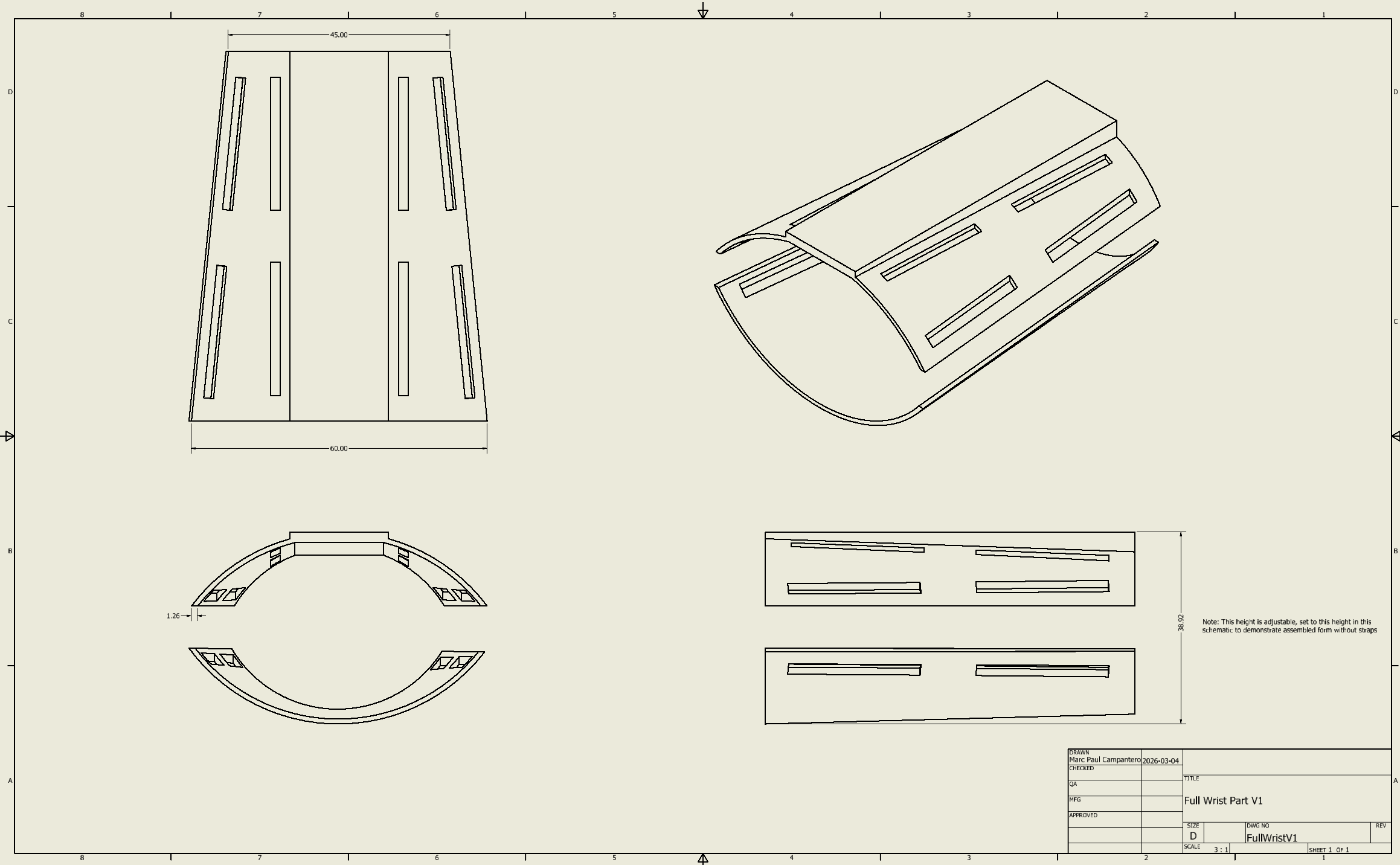
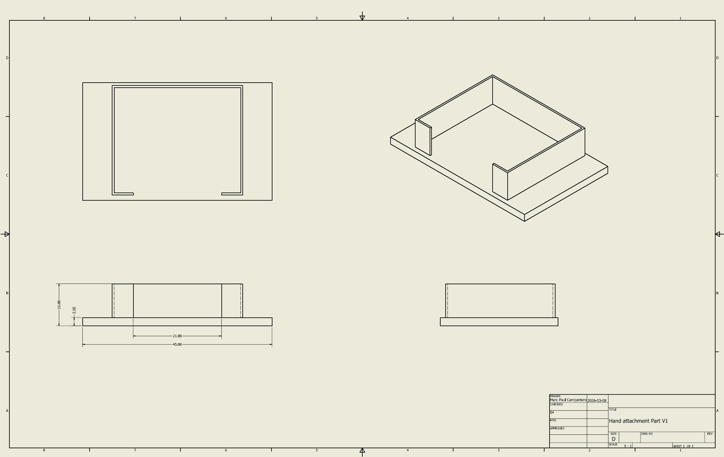
The device is a two-part system. A 3D-printed PLA forearm brace houses an ESP32 microcontroller and a BNO055 9-DOF IMU. A second, smaller hand module holds another BNO055. The ESP32 reads accelerometer vectors from both sensors over I2C, computes a tilt angle for each using atan2, and subtracts one from the other to get the relative wrist angle; that difference becomes the flexion or extension measurement.
The shell geometry tapers toward the wrist, has ventilation slots cut into the top for breathability, and features strap mounting slots along the sides. Mechanically, the brace restricts radial and ulnar deviation to within 5 degrees of neutral while permitting controlled sagittal-plane movement: flexion up to 80 degrees and extension up to 70 degrees.
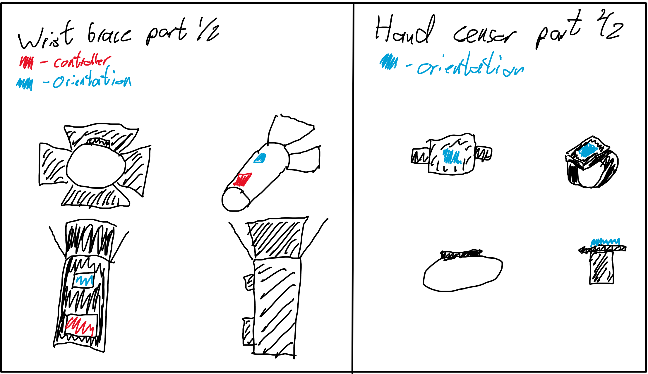
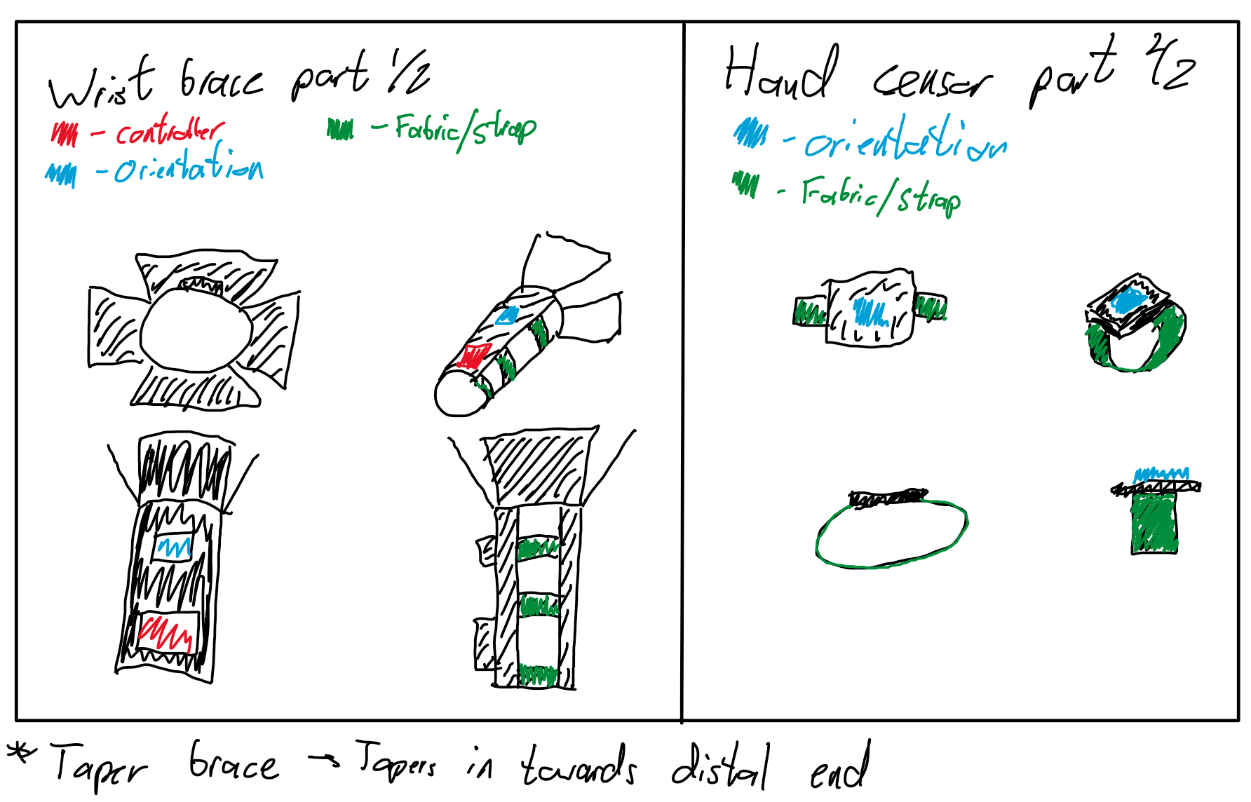
These sketches were done early to communicate the concept before any CAD work started. They helped us align on the form factor as a team.
Marc led the CAD. I was mostly involved on the electronics side: where the sensors sit, how the wiring routes, and how the I2C lines connect back to the ESP32.
What I Did
My individual contributions across the project.
Firmware and Sensor Integration
I wrote the ESP32 firmware that reads accelerometer data from both BNO055 sensors and computes the wrist angle in real time. The approach uses raw accelerometer vectors and atan2 to derive a tilt angle for each sensor independently, then subtracts one from the other to get the relative wrist angle. This avoids relying on the BNO055's internal fusion output, which we found was less stable when two sensors were running simultaneously on the same bus. I liked this part of the project because it felt the most concrete; if the code was wrong, the device was wrong.
One problem we hit early was that both BNO055 sensors ship with the same default I2C address (0x28). The ESP32 has a single I2C bus, so wiring both sensors directly meant address collisions. The fix was pulling the ADR pin high on one sensor to shift it to 0x29. It sounds minor on paper, but it blocked us for a full afternoon before we sorted it out.
#include <Wire.h>
#include <Adafruit_Sensor.h>
#include <Adafruit_BNO055.h>
#include <utility/imumaths.h>
#include <math.h>

float theta_hand;
float theta_arm;
float theta_wrist;

Adafruit_BNO055 imu1 = Adafruit_BNO055(55, 0x28);
Adafruit_BNO055 imu2 = Adafruit_BNO055(56, 0x29);

unsigned long previousTime = 0;
unsigned long startTime = 0;
const unsigned long interval = 100;The calibration loop waits until both accelerometers report a calibration level of at least 2 before starting measurements. Once calibrated, we recorded the neutral offset at 0 degrees (the device reading when the wrist is flat), then used that as a manual correction factor in our Excel analysis. During verification, I had the serial output piped into a logging script on my laptop, which made the test feel much more controlled; we could focus on holding the angles properly instead of scrambling to copy numbers.
Design Review Liaison and Note-Taking
Across all three design reviews, I was the one taking notes and acting as the go-between for our TA and the team. I would write everything down during the session, organize the feedback into action items, and make sure it all ended up in our design history file. Below is an excerpt from my notes during the Week 8 review, where our TA pushed us to rethink how we framed our verification.
week 8 design review - milestone 3 feedback
- ta says verification cant be yes/no answers
- "does it reach 80 degrees" is not a real verification question
- reframe: does device maintain accuracy across the FULL range
- separate range verification from accuracy verification
- range = does device allow 0-80 flex, 0-70 ext
- accuracy = at each angle, how close to goniometer
- both need to pass for overall verification to pass
- frame like a flowchart: range AND accuracy = verified
- use measurable metrics (angular error, variance) not yes/no
- radial/ulnar restriction still relevant but secondary
- repeatability (std dev of 3 trials) separate from accuracy
- could split flex and ext into two DIs that both must pass
action items:
1. rewrite DI-01a/DI-01b for range eval not threshold
2. quantitative test method vs goniometer
3. all results as measurable metrics
4. update verification docs, push to DHF
I kept notes like this for every design review and turned them into the formal action items in our milestone submissions. It kept us aligned and made sure nothing got lost between feedback sessions.
Economic Analysis
I built most of the economic analysis. We evaluated three alternatives over a 5-year timeline: in-house production, outsourced manufacturing, and doing nothing. Each had a full cash flow model in Excel, evaluated with present worth analysis at the 8% MARR. I sourced real component prices, estimated production rates given our 10 hours/week constraint, calculated loan interest from current bank rates, and worked out whether the $20,000 investment from the project scope could yield a reasonable return. This was the part of the course that surprised me most; I did not expect the financial side to change how I thought about the design as much as it did.
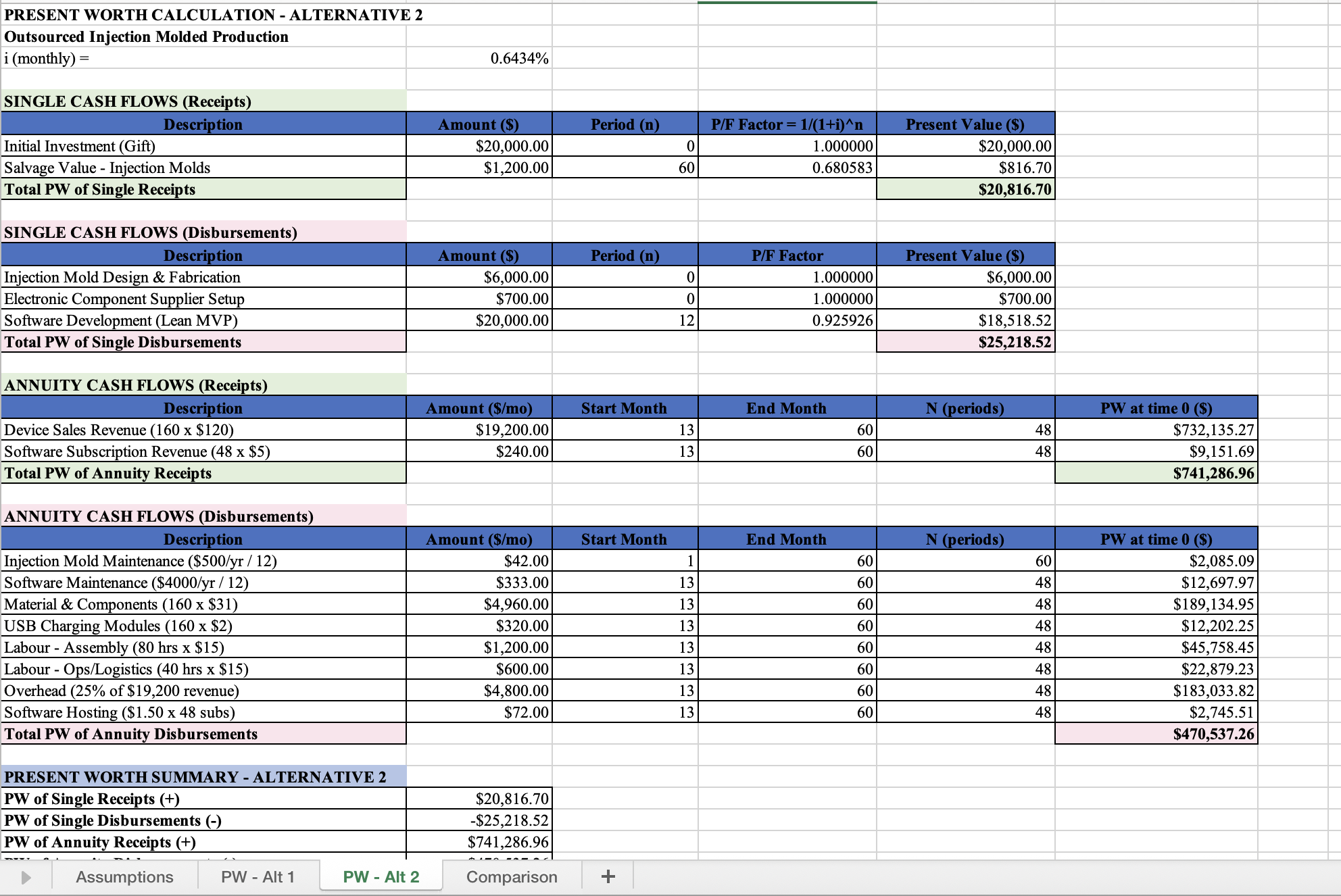
Outsourcing won because it eliminated capital equipment costs and let us scale without increasing our own time. The in-house option was cheaper per unit but required more hours than we could realistically commit. This fed directly into our oral presentation, where we walked the panel through the cash flow diagrams and comparison results.
Design History File
Marc and I maintained our design history file through the whole semester. Every milestone, every version of the design inputs table, every design review action item, every FMEA update ended up there. It was not glamorous work, but it forced me to understand the traceability between what we said we would build and what we actually built. By the time we got to the final report, having a well-organized DHF meant I could trace any design output back through design inputs to its original customer requirement. I did not appreciate that kind of documentation discipline until I needed it for real.
Verification
We verified one core design input split across two sub-criteria. DI-01a: wrist flexion measurement accuracy over 0 to 60 degrees. DI-01b: wrist extension measurement accuracy over 0 to 60 degrees. Each reading was compared against a manual goniometer using a ±5% error target at the tested positions. We tested at 20-degree increments (-60, -40, -20, +20, +40, +60), ran two trials per angle, and recorded the raw device reading at each position. Once we finally narrowed the scope to this one test, the whole verification plan made a lot more sense.
After calibration, the device reports a raw angle that includes a neutral offset. We recorded this offset at 0 degrees and subtracted it in Excel to get the corrected device reading. From there, we computed the absolute error and percent error at each angle. We also used mean absolute error as a summary metric across the full set, but it was not the same thing as the ±5% row-level check. Clarifying that distinction took us longer than it should have, but once we fixed it, the verification story became much easier to explain.
Verification check: single-angle walkthrough
Pick one of the tested angles and a trial to see how the measurement math works. This follows the same process we used in our Excel log.
The full verification used all six angles, both trials. The final pass/fail decision came from the full verification set, not from any single row shown here.
The protocol itself was shaped by the design review feedback I documented above. Before that conversation, we were going to check if the device "reaches 80 degrees" and call it done. After the review, we had a proper quantitative protocol with 20-degree increments, two trials per angle, a manual offset correction, and a real comparison against the goniometer. It made our results useful instead of trivial, and it also made me realize how easy it is to confuse a demo with a real verification plan.
Reflection
Looking back, the thing I keep thinking about is the gap between design intent and design reality. Our design inputs were clean, well-defined, and traceable; the actual prototype was held together with velcro and optimism. I do not think that was a failure. It was just the reality of what a verification prototype looked like at this stage. The whole point was never to ship a product. The point was to answer three questions with evidence: is it correct, is it safe, and does it make financial sense.
If I could go back to the start of the semester, I would push harder on the mechanical design earlier. We spent a lot of time refining design inputs and the verification plan, which was necessary, but the physical prototype came together in a compressed window toward the end. Marc's CAD was solid, but integrating the electronics housing into the printed shell was something we kept deferring. By the time we got to verification, I was mounting sensors with double-sided tape and hoping the straps held. It worked, but it was not the clean integration I had imagined when we were sketching; if I had another pass at the project, that is where I would start sooner.
The design review process was more valuable than I expected. I had treated design reviews in past courses as checkboxes. Here, the feedback actually changed what we built. When our TA pushed us to stop framing verification as pass/fail and instead quantify performance across the full range, it restructured our entire testing plan. I wonder sometimes whether I would have gotten to that framing on my own, or whether it took someone outside the team to challenge our thinking. Probably the latter. The feedback loop between presenting your work and having someone question your assumptions is something I undervalued before this course.
The economics portion was a reality check. Running the numbers on production costs, even at a modest scale, made it clear how thin margins are for hardware products. The outsourcing alternative came out ahead, but the projected returns were modest enough that it would be a tough sell for students with competing priorities. I think the exercise was less about whether the numbers said "yes" or "no" and more about learning to structure a financial decision systematically. Before this, I had never built a cash flow model or compared alternatives using present worth; now I could do it without feeling intimidated by it.
Working with Kusha, Marc, and Andrew taught me something about team dynamics I would not have learned solo. We had different strengths and different working styles. I leaned into the code and the economics because those felt natural. Marc drove the CAD. Kusha kept our milestone submissions structured and caught formatting issues I would have missed. Andrew helped with risk analysis and debugged sensor wiring with me during assembly. It was not always smooth, but it was functional and honest, which is about as much as you can ask for in a 12-week team project.
The question the course kept asking was "should you pursue this?" After verification, risk management, and the economic analysis, our answer was a cautious yes for the outsourced option, with caveats about scale and time. The device works; the risks are manageable; the money is tight. Whether students would actually pull the trigger on this venture is a separate question, and I am still not fully sure. What I am sure about is the value of arriving at that answer with real data instead of gut feeling.
Skills Developed
Embedded Systems
ESP32 firmware, dual-sensor I2C addressing, BNO055 calibration and accelerometer-based angle computation.
Design Controls
Translating customer requirements into traceable design inputs, outputs, and verification protocols.
Engineering Economics
Present worth analysis, cash flow modeling across alternatives, MARR-based comparison in Excel.
Risk Management
FMEA development, severity/probability classification, mitigation planning for unacceptable risks.
Technical Communication
Milestone reports, oral presentations, design review documentation, final written report.
Documentation
Maintaining a versioned design history file with full traceability across the semester.